The damage to network security occurs frequently and increases daily, as well as the damage scale. Therefore, there has been an increasing interest in network security, and many protocols are at development to ensure security in mobile networks. However, many security issues are remaining. Mobile networks should have reduced handover delay times in order to provide good quality of service (QoS) to users, but with current security protocol developments, the handover delay time is increasing, which leads to lower QoS. This paper proposes a protocol that supports good security with fast handover in Mobile IPv6 based networks and juxtaposition host based protocol (Hierarchical Mobile IPv6) and network based (Proxy Mobile IPv6).
Keywords: Fast handover for MIPv6, Network Security, Return Routerablity,Hierarchical Mobile IPv6,Proxy Mobile IPv6 and quality of service (QoS)Local Mobility Anchor (LMA), Local Mobility Domain(LMD), Mobile Access Gateway (MAG), proxy Home Address (pHoA), Host Negotiation Protocol (HNP), Binding Update (BU), Proxy Router Advertisement (PrRtAdv), Router Solicitation for Proxy (RtSolPr).
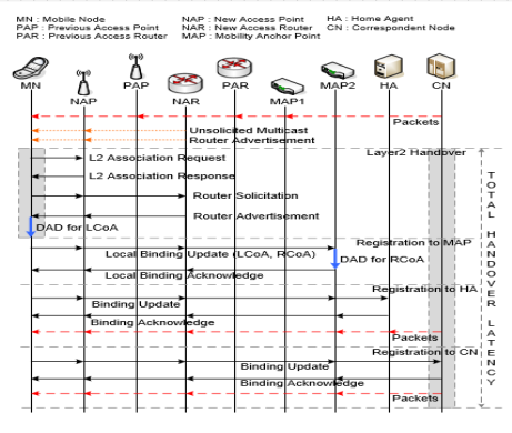
The packet delivery procedure in HMIPv6 (Figure 1): The packets sent from the CN are delivered to the HA since the current location information of the MN is not in the binding cache of the CN. Note that the BUR for the CN occurs after the completion of the route optimization (RO) with the CN. The HA forwards the packets sent from the CN to the MAP since the HA only knows the RCoA as the current location information of the MN. As soon as the packets arrive at the MAP, they are forwarded to the MN via the bi-directional tunnel established between the MAP and the MN. Then, the MN finally receives the packets through the tunnel. For instance, when the CN sends the packets to the MN located in the access link of AR1, the packets are firstly delivered to the HA where they are encapsulated to forward to the MAP. Then, the packets are encapsulated in the MAP once more and hence the MN receives the two-level encapsulated packets from the MAP before the completion of the RO with the CN. Note that the MN performs the RO procedure with the CN after receiving these non-optimized packets. The MN can hand off from the AR1 to the AR2 or AR3. In such cases, the packets are delivered via the newly established tunnel between the MAP and the MN due to the effect of the BUL procedure [1, 2].
The MAP only reduces the intra-domain signaling. When the MN moves out from the MAP domain, the effectiveness of HMIPv6 disappears. The MN, which hands off between different MAP domains, i.e., inter-domain handoff, needs to perform the BUR procedure for its HA and CNs as well as the BUL procedure for the new MAP [3].

The location update procedure in PMIPv6: As the MN hands off to the LMD, the serving MAG sends a PBU message to its LMA. This causes the LMA to recognize that the MN is now under the MAG so that the LMA can manage its binding cache entry for the MN for managing the session and routing information. Hence, the LMA on receiving the PBU message allocates the home network prefix (HNP) and sets up its binding cache entry for the MN. The LMA sends a proxy binding acknowledgement (PBA) message as a receipt of successful location update for the MN so that the bi-directional tunnel between the MAG and the LMA is established. The created bi-directional tunnel is used for routing the packets to and from the MN. After the location update procedure has occurred between the MAG and the LMA, the MN receives the RA message including the HNP on the access link of the MAG. Then, the MN creates its proxy home address (pHoA) based on the HNP. For instance, as the MN attaches to the access link of MAG1, the location update procedure between theMAG1 and the LMA is performed. Then, the MN.
1-Figure. Hierarchal Mobile IPv6
Configures its pHoA based on the HNP included in the RA message. If the MN hands off from the MAG1 to the MAG2 in the given LMD, the MAG2 also sends a PBU message to the LMA and then the bi-directional tunnel between theMAG2 and the LMA is established for the MN’s packet routing. Even though the MN changes its access link, the MN receives the same HNP in the RA message sent from the MAG2. In other words, the MN continually obtains the same pHoA that has been configured in the previous access link so that the MN can hand off without requiring participating in any mobility related signaling whenever it hands off within the LMD.
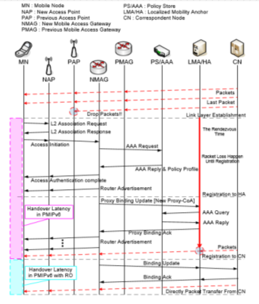
The packet delivery procedure in PMIPv6 (Figure 2): The packets sent from the CN are naturally delivered to the LMA, since the LMA is a topological anchor point of the MN. Based on the binding cache entry of the LMA, the packets are forwarded to the serving MAG via the bi-directional tunnel for the MN. Note that the bi-directional tunnel endpoints are the addresses of the LMA and the serving MAG for the MN, respectively. Finally, the serving MAG sends the packets to the MN. In the case that the MN hands off from one MAG to another, the packets are delivered to the new location of the MN due to the effect of the location update procedure between the currently serving MAG for the MN and the LMA. For instance, when the CN sends the packets to the MN located at the access link of MAG1, the packets arrive at the LMA where they are encapsulated and then forwarded to the MAG1 through the bi-directional tunnel for the MN.

2-Figure. Proxy Mobile IPv6
Then, the packets are capsulated in theMAG1 and then finally the MN receives the packets sent from the CN. Even though the MN hands off to the access link of the MAG2, the MN can receive the packets through the bi-directional tunnel established between the MAG2 and the LMA.This is because the LMA forwards the packets to the precise tunnel for the MN and the MN still uses the same pHoA in the new access link. PMIPv6 provides its mobility service only in the LMD so when the MN moves out from one LMD to another one, the MN needs to perform the MIPv6 operation. In this case (inter-domain handoff), the LMA located in the MN’s home domain acts as the HA and the MN needs to send a BU message to register its new location [4,5].
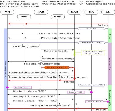
Proposed scheme operation. Figure 3 shows the processing procedure for the handover in the proposed scheme. When the MN detects movement, the MN sends RtSolPr message to the PAR. Then, the MN receive a PrRtAdv message from the PAR. The PrRtAdv message includes NAR’s Router Prefix value. The MN creates anNCoA. Then, the PAR sends a HI message to the NAR after the MN sends a FBU message to the PAR. The NAR performs the Look-Up Process for the NCoA. Then, the NAR sends a HAck message to the PAR. At the same time, the PAR sends a FBA message to the MN and the NAR. Then, the PAR sends packets to the NAR through the tunnel. When the MN moves to a new area, the MN sends a Router Solicitation and a Neighbor Advertisement message to the NAR. Then, the MN receives packets from the NAR after the MN receives the Router Advertisement with a Fast Neighbor Advertisement message from the NAR. The MN creates a “kG1” key to combine the MN’s MAC value and the NCoA.

3-Figure. The Proposed handover procedure scheme.
Then, the MN registers to the HA through a BU message. The BU message includes the “kG1” key. The HA creates a “kG2” key to combine the Home Address (HoA) and the NCoA. The MN receives the BA message from the HA. The BA message includes the “kG2” key. Then, MN sends the BU message to the CN. The BU message includes the “kG1”, and “kG2” keys. Then, the CN creates a “kG3” key to combine the CN’s Nonce Index and the NCoA. The CN sends packets to the MN after the CN sends a BA message to the MN. The BA message includes the “kG3” key. After this process, the MN and the CN know the “kG1”, “kG2”, and “kG3” keys.The CN encrypts packets and the MN decrypts packets through these three keys values. The proposed scheme provides enhanced security through key exchange process.
Table 1
Performance Analysis Parameters
|
Symbols |
Description |
Value |
|
t1 |
MNAP |
50ms |
|
t2 |
APAR |
40ms |
|
t3 |
ARAR |
60ms |
|
t4 |
AR HA |
50ms |
|
t5 |
AR CN |
50ms |
|
t6 |
LMA CN |
10ms |
|
tCoA |
FormingCoA |
1000ms |
|
tLook-Up |
BestValue |
3.36㎲ |
|
tLook-Up |
WorstValue |
5.28㎲ |
|
Α |
SignalWeightingfactor |
30ms |
|
Β |
PacketsRetransmissionrate |
100ms |
Proposed Scheme
= TL2_Tri + TReg + TLook_Up + THA_REG + TCN_REG
= 10t1 + 10t2 + 3t3 + 2t4 + 2t5 + tLook_Up
Hierarchical Mobile IPv6
The handover latency in the HMIPv6 is due to procedures that take place during the handover, which are:
1. Attachment notification Tattach = 4t1 + 2t2, where t1 is the communication time between the MN and NAP; and t2 between NAP and NAR. There is also a signal-weighting factor α, since the communication is in the Link Layer. (αTattach);
2. Duplicate Address Detection TDAD ;
3. MAP Registration TMAP = 2t1 + 2t2 + 2t3 + TDAD
3. Home Agent Registration THA = 2t1 + 2t2 + 2t3 + 2t4;
4. Followed by a registration to the CN TCN= 2t1 + 2t2 + 2t3 + 2t5
So, the handover latency in MIPv6: TMIPv6 = αTattach + 2TDAD + THA + TMAP + TCN = 2α(4t1 + 2t2) + 2TDAD + 6t1 + 6t2 + 6t3 + 2t4 + 2t5. After the movement, the handover latency remains the same, so the total latency handover for HMIPv6:
THMIPv6 = 2α (4t1 + 2t2) + 4TDAD + 12t1 + 12t2 + 12t3 + 4t4 + 4t5
Proxy Mobile IPv6
The handover latency in the PMIPv6 is due to procedures that take place during the handover, which are:
1. Attachment notification Tattach = 2t1, where t1 is the communication time between the MN and NAP; There is also a signal weighting factor α, since the communication is in the Link Layer. (αTattach);
2. Authentication Query and Authentication Reply due to the MAG verifying if the MN is eligible for the network-based mobility management service Tauth = 2t1 + 2t2 + 2t3, where t2 is the communication time between NAP and NMAG, and t3 is the communication time between NMAG and AAA;
3. Router Advertisement message delay Tra = t1 + t2;
4. Proxy binding registration delay Tbinding(LMA)2 = 2t4 + 2t5, where t4 is the NMAG and LMA communication time and t5 is between LMA and AAA;
5. Follow by another Router Advertisement message sent by the NMAG;
6. Followed by a Binding registration to the CN Tbinding(CN) = 2t4 + 2t6, where t6 is the communication time between LMA and CN;
So, the handover latency in Proxy Mobile IPv6: TPMIPv6 = αTattach + Tauth + 2Tra +Tbinding(LMA) + Tbinding(CN) = α(2t1) + 4t1 + 4t2 + 2t3 + 4t4 + 2t5 + 2t6. Futhermore, the handover after the movement inside the same LMD domain remains the same, so the total handover latency for the PMIPv6:
TPMIPv6 = 2α(4t1) + 8t1 + 8t2 + 4t3 + 8t4 + 4t5 + 4t6 .
Performance Comparison
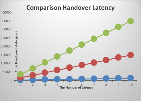
Figure 4 shows a graph comparing the changes in number of handovers. Proposed scheme is efficient more than Standard HMIPv6 and PMIPV6. The proposed scheme demonstrates more efficiency compared to standard protocols.

4-picture. Comparison Handover Latency.
References:
- C. Perkins, D. Johnson and J. Arkko, "Mobility Support in IPv6," IETF RFC 6275, July 2011
- R. Koodli, Ed., "Fast Handovers for Mobile IPv6", IETF RFC 4068, July 2005.
- Hyung-Heon Kim, Seok-Cheon Park, "RR Protocol by Using ECC Algorithm in Mobile IPv6".
- Sehwa Song, Hyoung-Kee Choi, "Secure Binding Update in Mobile IP version 6".
- Ilsun You, Yoshiaki Hori, Kouichi Sakurai, "State of Art on Security Protocols for Fast Mobile IPv6".


