Flux gate magnetometer is one of the instruments which have been installed on various mobile objects, in particular on aircrafts, spacecraft and rockets. This article will describe the current state of magnetic sensing within the earth’s field range and how these sensors are applied. Several applications will be presented for magnetic sensing in systems with emphasis on magnetic heading detection based on magnetic fields.
Key words: magnetic field, flux gate, ferromagnetic materials, anisotropic magneto-resistance, wheatstone bridge
This paper has described the present state of several methods of magnetic sensing and how they are used in various applications. An angular position sensor (also referred to as a rotary sensor) measures the relation by which any position with respect to any other position is established. It calculates the orientation of an object with respect to a specified reference position as expressed by the amount of rotation necessary to change from one orientation to the other about a specified axis.
There are many different kinds of angular position sensors. Many of the most common types categorized by supply voltage, output type, sensing range, operating temperature range, packaging type and supply current. Angular position sensors can be found in wide array of automotive and industrial applications also in aircraft navigation systems. Figure 2 is a flowchart of angle sensors, mainly in the form of optical, magnetic, inductive, capacitive, and resistive sensors.
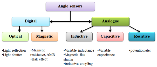
Fig. 1. Type of angle sensors
The magnetic range for the medium field sensors lends itself well to using the earth’s magnetic field. Several ways to use the earth’s field are to determine compass
headings for navigation, detect anomalies in it for vehicle detection, and measure the derivative of the change in field to determine yaw rate [1, 2].
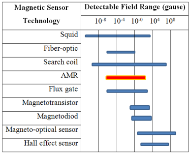
One way to classify the various magnetic sensors is by the field sensing range. These sensors can be arbitrarily divided into three categories — low field, medium field, and high field sensing. Sensors that detect magnetic fields less than 1 microgauss will be classed low field sensors. Sensors with a range of 1 microgauss to 10 gauss will be considered earth’s field sensors and sensors that detect fields above 10 gauss will be considered bias magnet field sensors for this article. Table 1 lists the various sensor technologies and illustrates the magnetic field sensing ranges (AMR sensor field range with red line).
A magnetic field is a vector quantity with both magnitude and direction. The scalar sensor measures the field's total magnitude but not its direction. The omnidirectional sensor measures the magnitude of the component of magnetization that lies along its sensitive axis. The bidirectional sensor includes direction in its measurements. The vector magnetic sensor incorporates two or three bidirectional detectors. Some magnetic sensors have a built-in threshold and produce an output only when it is surpassed [3].
Table 1
Magnetic sensor technology field ranges
Magnetic sensors have been in use for direction finding or navigation for centuries. The earth magnetic field is a weak three-dimensional field with an intensity of 50–60µT (0.5- 0.6 Gauss) that can be approximated by a dipole model.
Today, there are various types of electronic compasses available. The most commonly used magnetic field sensors for compass applications are based on the magneto resistive (AMR) effect, on the fluxgate effect or on magnetoinductive effect. Because of the weakness of the earth magnetic field Hall-effect sensors were hardly applied due to their poor sensitivity. It is generally believed that Hall sensors are only applicable at magnetic field higher than 0.5mT, and that the measured field must be perpendicular to the sensors surface.
Fluxgate magnetometers are the most widely used sensor for compass navigation systems of aircraft. Fluxgate sensors have also been used for geophysical prospecting and airborne magnetic field mapping. A magnetoinductive sensor is simply a single winding coil in a ferromagnetic core that changes permeability within the Earth's field.
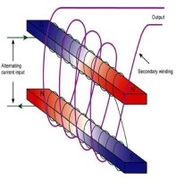
The magnetic induction of this core changes in the presence of an external magnetic field. A control signal is applied to the primary winding at frequency f (400 Hz in aviation) that causes the core to oscillate between saturation points. The secondary winding outputs a signal that is coupled through the core from the primary winding (simple flux gate magnetometer in Fig. 2). This signal is affected by any change in the core permeability (slope of B-H curve) and appears as an amplitude variation in the sense coil output.
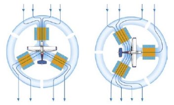
The flux gate is a small, segmented ring, like the one in Figure 2, made of soft iron that readily accepts lines of magnetic flux. An electrical coil is wound around each of the three legs to accept the current induced in this ring by the Earth’s magnetic field. A coil wound around the iron spacer in the center of the frame has 400 Hz alternating current (AC) flowing through it. During the times when this current reaches its peak, twice during each cycle, there is so much magnetism produced by this coil that the frame cannot accept the lines of flux from the Earth’s field. These three coils are connected in such a way that the current flowing in them changes as the heading of the aircraft changes.
a) b)
Fig. 2. Flux gate
a) simple flux gate b) the three-axis flux gate magnetometer
All flux gates use a highly permeable core which serves to concentrate the magnetic field to be measured. The core is magnetically saturated alternatively in opposing directions along any suitable axis, normally by means of an excitation coil controlled by a sine or square waveform. Ferromagnetic materials of high initial permeability are used as the sensor core. Permalloy, a kind of nickel-iron alloy (FeNi), has been most commonly used [4,5]. Table 2 shows component of permalloy.
Table 2.
Component of ferromagnetic material
|
Fe |
C |
Si |
Mn |
Ni |
S |
P |
Mo |
Ti |
Al |
Cu |
|
13,73–16,8 |
0,03 |
0,3–0,5 |
0,6–1,1 |
78,5–80 |
0,02 |
0,02 |
3,8–4,1 |
0,15 |
0,15 |
0,2 |
The anisotropic magnetoresistive (AMR) sensor is also one type that lends itself well to the earth’s field sensing range. AMR sensors are designed to operate in the earth’s field range with highsensitivity and low noise. These provide a clean magnetic signal to detect the field components or small perturbations. The strengths of the sensors are employed to detect presence, direction, and classification of vehicles.
Anisotropic magnetoresistance discovered in 1857 by William Thomson (Lord Kelvin) occurs in ferromagnetic materials. It is termed anisotropic because, in contrast to the previously known ordinarymagnetoresistance, it depends on the angle between the electric current and the magnetization direction.The AMR effect is described as a change in the scattering cross section of atomic orbitals distorted by the magnetic field as illustrated in Fig 3. The resistance produced by scattering is maximum when the magnetization direction is parallel (i.e. 0º or 180º) to the current direction and minimum when the magnetization is perpendicular to the current. In general, the resistance is given as a function of the angle, θ, between the magnetization and current:
![]() (1.1)
(1.1)
θ = 00 → Rmax
θ = 900 → Rmin
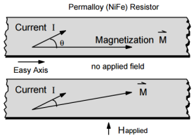
Fig. 3. Magnetoresistive effect
The architecture of an AMR sensor can be seen as two Wheatstone bridges. The angle can then be calculated using the two output voltages (Vx and Vy). Because of magnetoresistance, the resistance in the Wheatstone bridges changes when exposed to a magnetic field in a certain direction. The consequence of this is a potential difference between either side of the Wheatstone bridge. This voltage is dependent on the angle. The second Wheatstone bridge is oriented with a rotation of 45° compared to the first Wheatstone bridge. This layout is shown in figure 4. The result of this design is that the output voltages are two sinusoids with a difference of 90°.
![]()
Using processing circuit which can separately detects the x-, y-, and z-components of applied magnetic field, as shown in figure 4. The permalloy plates are set adjoining R1, R4 (not adjoining R2, R3) on the sensor surface. Assume that R >>ΔR, where R is the base resistance for R1~R4. Then, the potential deference between midpoints of each Wheatstone bridge is expressed as follows:
![]() (1)
(1)
![]() (2)
(2)
where ΔRx, ΔRy, and ΔRz are changes in resistance of AMR elements with respect to x-, y- and z-componentsof applied magnetic field, respectively. As shown in
Eqs. (1) and (2), output voltage of each bridge contains ΔRz component. The ΔRz can be calculated summing four midpoint potentials of two wheatstone bridges as follows:
![]() (3)
(3)
According to Eqs. (1)-(3), ΔRx, ΔRy, and ΔRz are separately obtained by knowing Vx, Vy, and Vz.
Magnetoresistance is the property of a material or system of materials that results in a change of resistance when exposed to a magnetic field. The discovery of large magnetoresistive effects has led to the development of solid-state magnetic sensors that can replace more expensive wire-wound sensors in a variety of applications.
Magnetoresistive sensors make use of the magnetoresistive effect, the property of a current carrying magnetic material (tipically Permalloy) to change its resistivity in the presence of an external magnetic field.
A characteristic of the Permalloy film is that it changes resistance (∆R) when exposed to a variation in an applied magnetic field hence the term magnetoresistance.
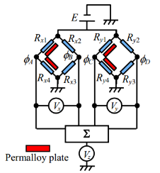
Fig. 4. Electrical circuit of AMR sensor
AMR sensors can detect dc static fields as the strength and direction of the earth magnetic field. This sensor is made of a nickel-iron (Permalloy) thin film deposited on a silicon wafer and is patterned as a resistive strip. The magnetic properties of the AMR thin film changes resistance by 2–3 % in the presence of a magnetic field.
AMR sensors provide an excellent means of measuring both linear and angular position and displacement in the earth’s magnetic field. Permalloy thin films deposited on a silicon substrate in various resistor bridge configurations provide highly predictable outputs when subjected to magnetic fields [6,7].
The principle of sensor is as follows: a permalloy plate is stood aside AMR element. The plate distorts magnetic field and generates x- (or y-) component from originally z-directional field. So, the resistance of MR element changes in proportional to z-axis field
intensity, provided that other axes intensities are kept constant. By contriving a processing circuit, three axes components can be separately detected.
Anisotropic Magnetoresistive (AMR) technology that provides advantages over other magnetic sensor technologies. These anisotropic, directional sensors feature precision in-axis sensitivity and linearity. These sensors’ solid-state construction with very low cross-axis sensitivity is designed to measure both the direction and the magnitude of Earth’s magnetic fields, from milli-gauss to 10 gauss. Magnetic Sensors are among the most sensitive and reliable low-field sensors in the industry.
For an electronic compass, the magnetic field sensor like AMR sensor has to have the following features:
‒ high accuracy and high sensitivity;
‒ to be small in size;
‒ have low power consumption;
‒ easy to combine and high reliability.
AMR sensors feature actually low hysteresis and high linearity for high measurement accuracy. The sensitivity of AMR sensors is very high up to 50 times higher than other solid-state magnetic sensors, such as Hall effect sensors. Sensitive AMR sensors can detect the earths magnetic field for compass applications and are also used succesfully in non-destructive testing and vehicle detection applications, where very weak magnetic fields must be accurately measured. AMR sensors can be specially designed with a high internal resistance, making them well suited to battery powered applications.
Conclusion. The ways of their improvements are analysed and we can get high sensitive also miniature magnetic heading sensor replacing ferromagnetic core of sensor with new multicomponently ferromagnetic of Ni3Fe structure. The magnetic alloy described in this paper is multicomponently composition of nickel and iron at magnetizing fields in the neighborhood of microgauss. A well-designed flux-gate magnetometer can sense a signal in the tens of microgauss range, as well as measure both magnitude and direction of static magnetic fields.
The specific advantages of AMR sensors already indicate their use in several navigation of aircraft applications. AMR sensors are designed to operate in the earth’s field range with high sensitivity and low noise. Nowadays anisotropic magnetoresistive sensors can replace traditional inductive sensors (flux gate magnetometers). These provide a clean magnetic signal to detect the field components for magnetic heading of aircraft or small perturbations.
References:
- D. J. Mapps, M. L. Watson, N. Fry, “A Double Bifilar Magneto-Resistor for Earth’s Field
- Detection” IEEE Trans. Mag., Vol. 23, pp. 2413–2418 (1987).
- J. E. Lenz, “A Review of Magnetic Sensors”, Proceedings of the IEEE, vol. 78, no.6, (June 1990) 973–989.
- B. B. Pant, “Magnetoresistive Sensors”, Scientific Honeyweller, vol. 8, no.1, (1987) 29–34.
- P. Ripka, “Review of Fluxgate Sensors”, Sensors and Actuators A, 33, (1996) 129–141.
- F. Primdahl, “The Fluxgate Magnetometer” J.Phys. E: Sci. Instrum., Vol. 12, pp. 241–253, 1979.
- P. Ciureanu, S. Middelhoek, “Thin Film Resistive Sensors”, 1992, New York: Institute of Physics Publishing.
- W. Thomson, «On the electrodynamic qualities of metals: effects of magnetization on the electric conductivity of nickel and iron», Proc. Roy. Soc. London, vol. 8, pp. 546–550, 1857.


