The article sets the task to consider the possibility of improving the technology of centering casing strings during well cementing. This is achieved by including hydromechanical centralizers in the casing rigging. The result is an increase in the reliability of the centralizer and the expansion of its operational capabilities.
Keywords: cementing, hydromechanical centralizer, casing string, technology, borehole.
One of the most important processes in developing a well for oil production is casing string cementing. Cementing is the process of filling a given interval with a solution of cementitious materials (such as cement), which at rest turns into a solid impenetrable stone. After hardening, the cementitious compound acquires a strong structure that reliably fixes the required casing interval. Cementing is used to isolate permeable formations and hold the casing in suspension.
The success of cementing in wells is determined by geological and technical factors. The degree of influence of these factors, the intensity and nature of their manifestations are very diverse even in the conditions of the same field.
To ensure uniform distribution of the cement slurry, the casing must be centered.
The centering of the columns contributes to the even distribution of cement around the casing, improves the quality of separation of the layers. In recent years, several techniques and instructions for centering casing in wells have been developed and published. One of the techniques discussed in this article.
The object of this work is to improve the technology of casing centering during well cementing.
By incorporating hydromechanical centralizers in the casing rigs, it is possible to improve the quality of the borehole wall fastening. This technology is relatively new, but hydromechanical centralizers are placed in the usual casing rig circuits with spring or rigid centralizers.
Hydromechanical centralizers are installed in an amount of at least 2–3 pieces, with the lower hydromechanical centralizer installed on the string at the level of the check valve, and the next ones above and below the casing perforation zone.
The performance of centralizers was evaluated in laboratory conditions using electromagnetic defectoscopy equipment EMDS-MP.
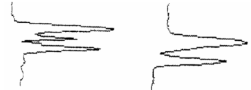
Studies have shown the reliable performance of centralizers: the obtained diagrams well record a noticeable difference between the signal from the open and unopened centralizer (Fig. 1)
The curves in the diagrams differ in shape and not in amplitude, which is very important, since the centralizers can be made of different metals.

Fig. 1 — Open and closed centralizer
To solve the above problems, it is proposed to include hydromechanical centralizers developed in the Zenit NPF LLC (Oktyabrsky city) in the technological equipment of the casing.
At the same time, the equipment scheme and the technology for attaching the casing of the well remain the same.
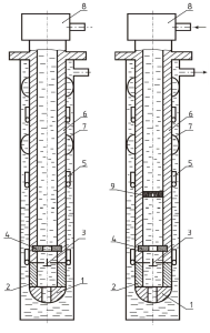
Cementing head 8 is mounted on the upper pipe of the casing 6. The calculated amount of cement is pumped into the casing. Following the cement slurry, cement plug 9 is inserted into the casing 6 and squeezing fluid is pumped over it, which is used to push the cement slurry into the annulus (Figure 1.2).
The passage of the cementing plug 9 of the installation sites of the hydromechanical centralizers 5 on the casing 6 is a signal to trigger them when creating a certain pressure drop between the casing and annular cavities.
Count the amount of displacement fluid that is pumped into the casing 6. When less than 3 m3 of pumped liquid remains, the rate of pumping is reduced. This process is called the “stop” moment and increased pressure at the wellhead 5.
At the time of increasing the pressure to the design at the mouth, the casing 6 lengthens, and the hydromechanical centralizers 5 are activated sequentially from top to bottom. At the same time, the casing is centered relative to the axis of the well and is anchored for the walls of the well at the installation sites of hydromechanical centralizers. At the same time, the casing will perform transverse decaying oscillations, since hydromechanical centralizers are a source of transverse vibrations of the string when they are triggered. Transverse damped casing vibrations contribute to obtaining a more uniform cement stone ring.
After the regulated time, the overpressure at the wellhead is vented and the anchored casing string is pulled over the borehole walls due to the elastic deformation of the string. The tightened state of the casing leads to a more uniform cement stone thickness, since the sagging of the casing in the inclined sections of the well between the centralizers decreases. It should be noted that when bleeding pressure at the wellhead with an anchored casing behind the walls of the well, the lower hydromechanical centralizer perceives the maximum axial load.
To communicate the cavity of the production casing with the reservoir after the cement slurry has solidified, holes are punched in it using perforators. In this case, part of the shock energy is diverted by levers of hydromechanical centralizers located above and below the perforation zone into the rock. Cementing using a hydromechanical centralizer is shown in Figure 1.2.

Fig. 2. Cementing a casing using a EMDS-MP
In the cementing process, the centralizer works as follows:
1) In the process of selling cement slurry, the cementing plug, passing inside the hydromechanical centralizer, cuts off the pins of the cork being destroyed;
2) After this, under the influence of the differential pressure of the annular and intra-annular fluid, the conical surface of the working piston acts on the ends of the levers. The levers move apart in the radial direction and abut against the walls of the borehole, thereby ensuring the location of the casing in the center relative to the axis of the borehole.
In the transport position, the centralizer arms are adjacent to the casing wall and improves the conditions for lowering the casing into the well.
The presence of hard centering levers in the centralizer ensures centering of the casing in the places where centralizers are installed concentrically to the well.
The casing is centered on the borehole wall, at this time the casing makes transverse damped vibrations, which contributes to a more uniform cement ring quality. After the centralizer is triggered, its bore has the same diameter as the casing. The quality of adhesion of cement stone to the column and rock is improved.
The casing string is tensioned, which ensures the correct operation of the threads of the production string during well operation. During perforation, part of the impact energy is diverted by levers of hydromechanical centralizers located above and below the perforation zone.
High-quality centering of casing strings in drilled wells plays a decisive role in ensuring the high efficiency of the technological process, as it helps isolate the productive object from neighboring horizons.
Studies have shown the reliable performance of centralizers. When hydromechanical centralizers are included in the equipment, the quality of fastening the walls of the well significantly increases. Centralizers contribute to obtaining a more uniform cement ring quality and improve the quality of adhesion of cement stone to the column and rock.
References:
- Bulatov, A.I. “The formation and operation of cement stone in the well”. — M.: Nedra, 1990.
- Alekseeva L. L. “Innovative technologies and materials in the construction industry: Textbook”. — Angarsk: AGTA, 2010.
- Babkov, V.V. “Structure and strength of cement stone”. — Ufa, 1979.
- Bazhenov, Y. M. “Concrete under dynamic loading”. — M.: Stroyizdat, 1970.
- Larin P. A., Shamsutdinov T. P., Stepanov R. R. “Hydromechanical centralizers like TGMS for casing”. — Ufa, 2006.
- Larin P. A., Stepanov R. R. “Laboratory and field tests of hydromechanical centralizers like TGMS”. — Ufa, 2006.
- Gelfgat Y. A., Gelfgat M. Y., Lopatin Y. S. «Advanced drilling solutions: lessons from the FSU», Volume 2, PennWell, 2003


