In this article, describe nanoplasmonics theory and how to use in solar cells. Besides, we calculate generation rate by nanoplasmonics in some materials.
Key words: nanoplasmonics, solar cell, generation rate, continuity equation
The motion equations of electrons and holes are determined by solving the drift-diffusion equations. These equations are based on the equation of continuity.
Jn=µn(n󠄷∇Ec-1.5nkT∇ln(mn))+Dn(∇n-n∇ln(γn)) (1)
Jp=µp(n󠄷∇Ev-1.5nkT∇ln(mp))+Dp(∇p-p∇ln(γp)) (2)
Here:
Jn and Jp are the current densities generated by electrons and holes.
µn and µp are the motions of electrons and holes.
mn and mp are the effective masses of electrons and holes.
Dn and Dp are the diffusion coefficients for electrons and holes.
Ec is the energy of the conduction band.
Ev is the energy of the valence band.
k is the Boltzmann constant.
T is temperature
γn and γp are fermi statistics for electrons and cavities and it is defined as follows for electrons and cavities.
γn=NC-1n*exp((EF,n-Ec)*k-1T-1) (4)
γp=Nv-1p*exp((Ev-EF,p)*k-1T-1) (5)
Here:
Nc is the density of cases in the conduction band
Nv is the valence zone case density
EF,n quasi-farm zone energy for n type
EF,p quasi-farm zone energy for p type
If we use Einstein's relation for electrons and holes, equations 1 and 2 look like this.
Dn=kTµn (6)
Dp=kTµp (7)
Jn=-nqµn∇Φn (8)
Jp=-pqµp∇Φp (9)
Here:
Φn and Φp are quasi-Fermi potentials for electrons and holes.
We can determine the potentials of a quasi-fermi using Boltzmann statistics.
The electrostatic potential is determined by the Poisson equation.
∇(ε∇φ+P)=-q(p-n+ND-NA)-ρtrap (10)
Here:
ε is the dielectric constant
P is the ferromagnetic polarity.
q is the elementary charge
ρtrap is the charge density due to defects.
φ is electrostatic potential.
If the medium in question is silicon, it is not a ferromagnetic substance and therefore does not have ferromagnetic polarity.
Δφ=-q*ε-1(p-n+ND-NA)- ρtrap*ε-1 (10)
The solution of the above equations gives us the volt-ampere characteristic.
Volt-aper characteristic for darkness:
J=J0*exp(U*q*k-1T-1) (11)
Assuming the light is falling:
J=J0*exp(U*q*k-1T-1)-Jph (12)
Where Jph is the photogeneration current density.
If the nanoparticles introduced into a solar cell represent an increase in its absorption coefficient, then the photogeneration current also changes. That is, it increases [3].
The nanoplasmonic effect can cause 3 different phenomena [2].
- Nanoparticles radiate light in a visible field due to incident light
- Or the emission of electrons due to incident light.
- Converts absorbed energy into heat
We know that the element silicon mainly absorbs light in the visible field. So through this we can increase the absorption coefficient of the solar cell.
The optical properties of solar cells are determined by the transfer matrix method. That is, its absorption, return, and transition coefficients are determined. The rate of generation is determined by the abstract part of the complex refractive index.
G0= αI(d)h-1ω-1 (13)
α=4πkλ-1 (14)
Here:
G0 is generation rate.
α is the absorption coefficient
k is the abstract part of the complex refractive index
λ is the wavelength
h is the Planck constant
I (d) is the intensity of the incident light.
ω is the cyclic frequency of the incident light.
So, given the nanoplasmonic effect, what frequency and energy does a nanoparticle emit first?
If we say that the share of the radiation phenomenon Csc, which is visible from the above 3 possible phenomena in the nanoplasmonic effect, then the radiant energy [1].
I(ω)=I0(ω)*S-1*Csc(ω) (15)
Here:
I (ω) is the energy intensity of the radiation
S — πr2 for effective surface nanoparticles
I0 (ω) is the intensity of light incident on the nanoparticle
Csc(ω)=k4(3V)2((ε’r-1)2+εr”2)*((2+ ε’r)2+ εr”2)-1*(6π)-1 (16)
Here:
k is the number of waves
V is the volume of the nanoparticle
ε’r is the true part of the complex dielectric constant
εr” is an abstract part of complex dielectric constant
Formula 16 was discovered in 1982 by Bohrenn and Huffman.
So if we combine all this, we can see that the absorption coefficient increases. Along with this, the generation rate also increases.
ΔG=α*N*I0(d)S-1Csch-1ω-1 (17)
Gum= ΔG+G0 (18)
Where N is the number of nanoparticles.
Gω= I0(ω) h-1ω-1(1+NS-1Csc(ω)exp(-αd)) (19)
The general generation is
Gum= ∫I0(ω) h-1ω-1(1+NS-1Csc(ω)exp(-αd))δω (20)
So the photocurrent density is
Jph=q*d*∫I0(ω) h-1ω-1(1+NS-1Csc(ω)exp(-αd))δω (21)
So, I-V characteristics
J=J0*exp(U*q*k-1T-1)- q*d*∫I0(ω) h-1ω-1(1+NS-1Csc(ω)exp(-αd))δω (22)
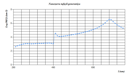
All results are taken by “Suntulip -2 for silicon solar cell” simulation program. We can see a result in fig 1. Besides, all results took logarithmic.

Fig 1. Extra generation by silver nanoparticles
References:
- M. I. Stockman, Nanofocusing of optical energy in tapered plasmonic waveguides. Phys. Rev. Lett. 93, 137404–1-4 (2004)
- F. de Angelis, M. Patrini, G. Das, I. Maksymov, M. Galli, L. Businaro, L. C. Andreani, E. Di Fabrizio, A hybrid plasmonic-photonic nanodevice for label-free detection of a few molecules. Nano Lett. 8, 2321–2327 (2008)
- Carsten Sonnichsen, Plasmons in metal nanostructures, Munching, 20 June 2001.


