In the article, authors try to determine the problems of measuring the physical parameters of high-voltage circuits
Key words: physical parameters, circuits.
The power supply is one of the main points of modern civilization. The key role in it is played by high-voltage power transmission lines. Regardless of the distance of the generating capacity from the end users, long conductors are required to connect them. As with any equipment, you need to monitor these lines, monitor their condition, and check the current parameters in the circuits. There are various unpleasant situations, such as lightning hitting a power line tower and others that need to be recorded.
Let us analyze the problem of measuring the physical parameters of high-voltage circuits by the example of measuring electric current. Methods for measuring currents in high-voltage lines exist, but they are not perfect. The main disadvantages are the high cost and large dimensions of the equipment. Most of these devices are manufactured using magnetoelectric system devices with shunts.
Shunts for high currents become bulky, heavy and expensive, so, for example, a shunt of the type 75SHS 6000 A weighs 24 kg. In addition, the use of shunts for high currents does not provide sufficient accuracy and the power loss in them is high.

Fig. 1
We would like to present a method for measuring current in high-voltage circuits, where the sensor will be a bismuth-containing ferrite garnet film.
The operation of our hypothetical scheme is based on the Faraday Effect (rotation of the plane of polarization).
In 1845, Michael Faraday discovered that linear polarized light propagating along a constant magnetic field in matter experiences a rotation of the plane of polarization.
The strongest rotation of the polarization plane is observed in very thin transparent layers of ferromagnets. A number of substances, including ferromagnets, have magnetic optical activity. The optical activity induced by the magnetic field is also shown in the Faraday Effect. This effect is reduced to the rotation of the plane of linear polarization of a light beam passing through a magneto-optical medium. The angle of rotation in the direction of the magnetic field along the beam is proportional to the strength of the magnetic field [1].

Fig. 2
A monochromatic beam (electromagnetic radiation with a very small frequency spread, ideally a single frequency) is applied from the laser (1). The beam goes along the optical fiber (9) and enters the collimator (2). With the help of the collimator, we get a beam of parallel light rays (3). The elementary collimator consists of a diaphragm (a small hole), which is located in the focus of the lens. Next, the beam enters the measuring element (4)
The measuring element itself consists of:
— bismuth-containing ferrite garnet film (6)
— a substrate that is much thicker than the film (5)
— special «shoe» (7)
Element (8) is the line whose parameters we are studying: under the influence of changing currents in high-voltage lines, a magnetic field arises. To prevent this field from scattering, we put a metal element (7). The magnetic field can change the domain structure of our film, the transparency.
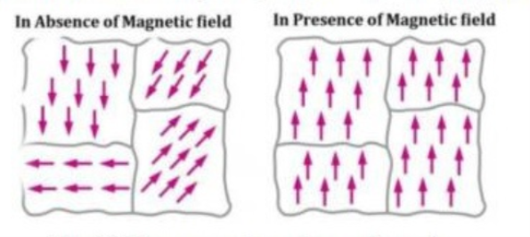
Ferrimagnets break up magnetically into many small macroscopic regions. Each region is spontaneously magnetized. These areas are called domains [2].

Fig. 3. Macroscopic regions — domains
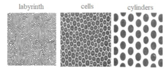
At a certain field strength (and, accordingly, at certain currents), the domain structure is labyrinthine, at certain-cylindrical there are other forms.Dark and light areas characterize the direction of magnetization.And here is the most interesting thing: the strength of the Faraday effect depends on the domain structure, that is, the rotation of the angle of the plane of polarization.The higher the current, the greater the magnetic field around the conductor, the greater the angle of rotation of the polarization plane.

Fig. 4. Types of domain structures
Now let's return to our beam: it falls on the film, and as it passes through the film, the angle of rotation of the plane of polarization changes (the Faraday effect), while the angle of rotation of the plane depends on the parameters in the circuit (current, voltage).Next, our long-suffering beam enters the fixing device (9), where information about the change in the parameters of our beam as it passes through the film is processed and transmitted. At the output, we can judge the magnitude of the current and voltage in the circuits.
So, to sum up a little: the operation of this scheme is based on the Faraday effect (rotation of the plane of polarization), and the sensor in our scheme is a bismuth-containing ferrite garnet film.
Литература:
1. Волькенштейн М. В. Молекулярная оптика. — Л.: Государственное издательство технико-теоретической литературы, 1951.
2. Преображенский А. А. Магнитные материалы. — М.: Издательство «Высшая школа», 1965.


