Difficulties in survey work performed for the design of linear objects can be caused by: the complexity of the terrain, the presence of thick vegetation cover,the lack of preservation of survey (geodetic) support nodes, and many other factors.
Conduct geodetic surveys and obtain all the necessary information for construction work.
Geodetic surveys on linear objects should be carried out along the entire route. For fast and high-quality execution of work, the widespread use of all kinds of innovative methods is currently envisaged. Including the use of devices such as tacheomer and GPS, aerial photography, laser scanners.
The article describes engineering surveying (geodetic) works developed for the design of works on the construction of a power line for the development of a field site. During the topographic work was carried out using traditional and modern methods. The territory where engineering geodetic work is carried out is distinguished by the complexity of the terrain. In the course of the work, a comparison of instrumental and modern shooting was made. The amount of Labor and costs for performing work was compared for conducting traditional shooting operations and when shooting using an unmanned aerial vehicle.
Keywords: linear objects, power line, tacheometer, aerial photography, orthophotoplane, track, digital model.
Introduction
Engineering and geodetic survey works are a set of works carried out for a natural and man-made assessment of a building site, for obtaining detailed information regarding the surface and underground communications of the site, the buildings in which it is located. Well, the purpose of the works is to confirm the correctness of the choice of the track and prepare all the necessary materials for the arrangement of structures. Geodetic and survey works are carried out for the design of all linear and district construction works [1].
Geodetic Survey works for the construction of linear objects — tracing, construction of a digital model of the terrain, obtaining a topographic plan. Linear objects include: iron or auto roads, engineering networks, etc. The axis of a linear object displayed on a map or on the Earth's surface is called a track [2].
The most important parts of the track are:
— the main point is the beginning, the starting point of the track.
— rotation angles-points that change the direction of rotation;
— the end of the track is a place to be designed and built.
According to the stages of engineering and geodetic survey work:
1. Preparatory stage:
a) obtaining a set task for conducting special work;
b) collection of archival materials related to the site;
c) preparation of the plot scheme;
2. Field main stage:
a) exploration of the territory;
b) development of reference Geodetic networks, height survey plan;
c) conducting topographic surveys;
d) monitoring the complete accumulation of information necessary for the topographic plan.
3. Cameral processing works:
a) creation of a topographic plan (computer processing of information collected from field work)
b) verification of full filling and accuracy of information related to engineering works located on the site;
c) complete collection of materials of all works performed and development for the customer.
Search works for power supply of the field site were carried out in Kerbulak district, Zhetysu region. The site is located along the Almaty-Ust-Kamenogorsk highway, in the small village of Karymsak. The Working Area begins from the fields along the Saryozek-Zharkent highway in a northeast direction towards the mountains. If there are intersections with hydrographic objects along the designed route, then further the terrain is transferred to Foothills and hilly areas.
Materials and methods
The purpose of engineering and geodetic surveys is to confirm the correctness of the choice of construction sites, tracks and obtain the necessary materials to justify the location (location) of structures.
Topographic survey for the design of the working project was carried out by a combined method — by the method of Tacheometric survey using electronic tacheometers and by the method of HNS-survey in RTK mode using GNS-equipment, aerial photography using a quadcopter.
Geodetic-class satellite navigation equipment was used in the measurements.
Temporary Geodetic points were fixed as points of Geodetic justification of the survey.
The measurement was carried out in RTK (real-time) mode, by beam positioning. A triangulation point was adopted to establish the surveying rationale for the survey.
All descent points of the base are determined using GNSS equipment with control (double, triple) dimensions from the starting points of no more than 10 km, which in planned conditions ensures the accuracy of the base at an altitude not lower than the accuracy of the scale of 1:5000 and not lower than the accuracy of technical leveling.
The overwhelming number of measurements were performed in RTK (real-time) mode by beam positioning. During the work, the following necessary control conditions were observed:
— the maximum distance between receivers is 10.0 km;
— the minimum number of satellites for processing is 8;
— recording interval — 1 sec;
— mask at height angle — 10 degrees;
— accuracy of obtaining coordinates:
— in the plan-0.02 m;
— in height-0.02 m;
— GDOP (satellite geometry) — less than 8.
Topographic survey of the design area, passages, and corridor of the route was performed by a combined method of Tacheometric survey using electronic tacheometers in RTK mode using two-frequency HNSS receivers and HNSS shooting. The shooting was carried out in the presence of 8 and more working satellites.
At the beginning and end of the work of the base station, control measurements were carried out at the fixed points of the shooting justification.
Aerial photography technology based on unmanned aerial vehicles consists of the following stages: preparatory work (site survey; preparation of Maps, design of flight routes and calculation of photographic elements); field work (fixing and coordination of signs, or installation of a base station, take-off); cameral work (processing of Geodetic measurement results, photogrammetric processing of images).
Signs are fixed and coordinated using GPS equipment using the satellite tracking method. The number of marks depends on the size of the working area, the required accuracy and shooting mode.
Results
When performing engineering and geodetic work, tacheometers and HNS devices were used to carry out traditional types of surveys, while modern surveys were carried out using the Mavic 2 Pro unmanned aerial vehicle.
For aerial photography, 66 signs were attached to the Earth's surface, the coordinates of which were determined using a GPS device. Next, the work to be done is to establish a route with respect to the route. To carry out this work, we use the Special Program «UgCS for DJI». The program allows you to create a route and track the movement of the instrument. The UAV created 9 routes along the entire route, as a result of which 4908 images were obtained [3].
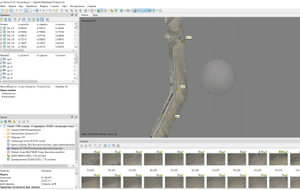
For in-house work, we use the Agisoft Metashape program and start processing. First, we start by uploading the photos in full and selecting them. Next, work on combining images, entering the coordinates of fixed signs, obtaining dense cloud points, constructing a numerical model, and obtaining an orthophotoplan. The placement of signs attached to the surface of the earth in the program is shown in Figure 1.

Figure 1. Inserting symbols in the Agisoft Metashape program
According to the results of aerial photography, the orthophotoplan of the track can be seen in Figure 2. Using orthophotoplanes, you can get a 3D view of the Earth's surface.

Figure 2. Orthophotoplan
As a result of aerial survey work in the Agisoft Metashape program, a digital model of the Earth's surface was created with an accuracy of 3–6 cm with a plan and 7–18 CM in height.
Conclusion
It is not possible to carry out engineering and geodetic surveys using only aerial surveys. As a result of combining various and modern types of shooting, it was found that in the work on the descent of the track, which was selected with a length of 215 km and a width of 100 m, the speed of work and the possibility of quick success with a small number of specialists are possible. The duration of the work can be seen in Table 1.
Table 1
|
Order of work |
Duration of work |
Number of people |
|
Joint survey of the UAV and the Earth's surface |
||
|
Fixing signs |
2 days |
1 |
|
Aerial photography |
2 days |
2 |
|
Processing of aerial photography results |
4 days |
1 |
|
Decryption and determination of engineering networks |
2 days |
2 |
|
Obtaining a topoplane |
2 days |
1 |
|
Total |
12 days |
2 |
|
Traditional shooting works |
||
|
Creation of Geodetic networks |
3 days |
2 |
|
Tacheometric survey |
15 days |
4 |
|
Determination of engineering networks |
3 days |
2 |
|
Obtaining a topographic plan |
10 days |
2 |
|
Total |
21 days |
5 |
References:
- М. А. Шубин Инженерные изыскания для строительства учебное пособие 2016г стр 17.
- Tashpulatov S. A., Kadyrov A. A. The composition of engineering and geodetic surveys of linear structures // Galaxy international interdisciplinary research journal (GIIRJ). 2021. Page 1254–1256.
- Osennia A. V., Korchagina E. V. airborne laser location and digital aerial photography. the advantages and disadvantages of the method // Science. Technique. Technology (Polytechnic Bulletin). 2015. No. 2. P. 42–44


