Radio extension unit simulation
Авторы: Чегодаев Николай Игоревич, Цебренко Константин Николаевич
Рубрика: 1. Информатика и кибернетика
Опубликовано в
II международная научная конференция «Технические науки в России и за рубежом» (Москва, ноябрь 2012)
Статья просмотрена: 44 раза
Библиографическое описание:
Чегодаев, Н. И. Radio extension unit simulation / Н. И. Чегодаев, К. Н. Цебренко. — Текст : непосредственный // Технические науки в России и за рубежом : материалы II Междунар. науч. конф. (г. Москва, ноябрь 2012 г.). — Москва : Буки-Веди, 2012. — С. 24-28. — URL: https://moluch.ru/conf/tech/archive/55/2839/ (дата обращения: 24.04.2025).
Informational support for rural economic activity establishments is still an actual task in Russian Federation remote localities. As quoted in previous publications there is a necessity of reliable telephonic services with a reasonable price for its acquiring and maintaining [1].
There is a possibility to familiarize oneself with full operational description for the noted device in previous publications. There is only short description quoted hereafter.
The radio extension unit device is designed for purposes carrying the nature of wired telephonic line over the duplex radio path with the feature of conversation retransmitting. As distinct from counterpart analogues the device designed without any signal preprocessing. Author’s experience in a similar devices utilization shows unstable operational results in certain circumstances. The radio-extender device includes two opposite modules: the basic one and the subscriber one. These two modules are submitted to embody the unit as the whole. The subscriber module connects to an ordinary phone, which represents the control console for the subscriber and maintainer purposes, such as line selecting. The place of the basic module locates near the wired telephonic line spot for transporting its options, standard signals and calls as it is to the subscriber’s phone. The radio-extender had designed to include two possible operation modes: the outgoing one and ingoing one. In outgoing mode the operator (or, possibly, the subscriber) takes up a hand-set and determines which one telephonic line to use with help of a keypad of an ordinary phone. The subscriber workaround is set to be much closer to the ordinary phone, which is used as a main part of the system. The basic and subscriber modules are connected by a common transceivers operating on a common frequencies allowed to the user [1].
In previous publications [1-3] author had made an attempt to describe the links in the device specified. Efforts were related to both continuous and discontinuous processes. As quoted in the records of International correspondence scientific conference «Technical sciences: traditions and innovations» (January 2012), model prototyping was determined to be stepwise [1, p. 49]. In this case it is necessary to review the previous articles associated with the building of the mathematical model of radio path shaping for audio information transmitting and radio-telephonic path shaping, which were quoted in the records of scientific conference, hereinabove.
The mathematical model shaping
and associated descriptions were provided by the records of the
scientific conference «Technical sciences: traditions and
innovations» (January 2012). There was a digest related to
continuous processes model quoted. Mathematical analysis of the given
model formulae defined by the article related to mathematical model
building up [2]. Mathematic dependencies for discontinuous processes
simulation described by an appropriate article [3] as A-automata
synthesis as a design of eight aggregates with the description
formula
![]() ,
where the second number (four) represents a quantity of an aggregates
for a given subsystem (both subscriber and basic ones) [3]. This
article concludes a set of publications related to mathematical
simulation for the radio-extender inner processes, if circumstances
of insuperable force would not oblige the author to continue these
publications.
,
where the second number (four) represents a quantity of an aggregates
for a given subsystem (both subscriber and basic ones) [3]. This
article concludes a set of publications related to mathematical
simulation for the radio-extender inner processes, if circumstances
of insuperable force would not oblige the author to continue these
publications.
The actuality topics are also within-named in previous publications. So, only a short refreshing note will be provided next. Building of a radio-extender simulation is necessary, by the reason of providing an area of necessary theoretical experiments. They will be compared with the data obtained from possibly natural efforts to shape a realistic model.
Let us provide a description of a raw data for simulation development. It is decided, that the simulation process will flow in a range from 0 to 1000 milliseconds due to the necessities to demonstrate the most adequate part of the process without a ornate-ness possibility. As already quoted [2] a vibratory operation of both voice and dual-tone multi-frequency signals (DTMF) can be described, approximately, as an oscillatory circuits [1]. The signal flow variations, however, should be concretized as a cosine oriented procedures for following interpretation as a part of the Fourier analysis to detect the reference token value. Indeed «voice» simulation leads to a complex signals composed of a several simple ones. This simple cosine signals were limited in quantity by possibly non ornate-ness two [2], there is an opportunity for the program operator to change frequency value of each. There is also a possibility to show complex signal in a mixed mode or as two individual plain signals.
The operator can concretize the amplitude value as well as the flow step for an individual cause. The phase shifting could be changed, also. As for modulation purposes, so, for formerly quoted entry for amplitude modulation (AM), it is possible to define a carrier frequency and modulation factor.
For the purposes of image zoom there should be a feature of scale changing for both X and Y coordinates.
The equation limitations mentioned in the article [2] won’t be introduced to simulation with the intent of experience them during simulation, for example, to demonstrate oneself an over modulation by providing an illegal modulation factor.
Signal processing and analysis represented as Fourier analysis [2, p.61] of a special case. An indication for the correct sequence detected is allowed. Correct sequence detection developed by a reference value as quoted above.
Timing derivations [3] are introduced to simulation as an event sequence integrated to program logic and a switch for statistical analysis mode and semi-realistic mode is provided, also.
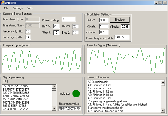
The main simulation view in the semi-realistic outgoing call mode and with all the input data provided by default is shown on figure 1.
Apparently, by an icon in left top corner, one can conclude that the simulation program is developed with Microsoft C# programming language. Indeed, it is so. Microsoft C# was chosen as the basis of a simulation for its slightly modern design, popularity and tight integration to the Microsoft Windows operating system.
As shown by figure 1, there are all the described above functions present with an appropriate controls.
Obviously, the signal parameters, such as the frequencies of the first and second parts of a complex signal and phase shifts can be variated by the operator.
The simulation process could be initiated by pressing the button «Simulate» and with a short period diagrams will appear on the screen. It needs to be quoted, however, that, if user chooses a semi-realistic simulation mode by selecting «Settings» → «Operating mode» → «A0-Outgoing call» or «A0-Ingoing call», there is no guarantee for the diagrams to appear, because of the distinctive features of a simulation process, which were quoted hereafter. In this case, user might press the button again to change the conditions. All the process noted above will not occur for the operator in case of a statistic analyses or in workaround with aggregates disabled.
An adjustment of the simulation can be manually executed with «Settings» menu. The short description of the functionality provided there is quoted by Table 1.
Table 1
The «Settings» menu
|
Option |
Set of choices |
Short description |
|
«Integrate» |
«True» |
By this setting user allow the program to draw a complex cosine signal instead of its two parts. |
|
«False» |
By this setting user forbids the program of drawing a complex cosine signal and instead it draws the signal’s entries. |
|
|
«Operating mode» |
«Aggregates disabled» |
In this mode there will be no simulation based on the timing formulae of a discontinuous processes described in article [3]. |
|
«Outgoing call» |
This option enables an outgoing call mode (a call initiated by an operator) simulation by statistical analyses with ej – basis at all [3]. |
|
|
«Ingoing call» |
This option enables an ingoing call mode (a remote call (initiated by a basic module[1]) obtained by an operator equipped with a common phone) simulation by statistical analyses with ej – basis at all [3]. |
|
|
«A0-Outgoing call» |
The same definitions as for outgoing call mode with allowance for ej – basis[3]. |
|
|
«A0-Ingoing call» |
The same definitions as for ingoing call mode with allowance for ej – basis[3]. |
|
|
«Execution timing factor» |
Can be set manually |
The option defines an average value based upon genuine microchips timings. |
|
«Queue Langth» |
Can be set manually |
The option defines an average value based upon genuine microcontrollers parallel computing factors [3], (see manual). |
As for the Table 1, there is a necessity to describe «A0-*» operation modes here. As noted by the article related to timing execution methods [3], in a the given formulae ej statement is present. The ej statement describes a functionality measures related to random values [3, p. 48]. This play of chance are strictly limited to three states or cases depended to outer environment [1] , which is current circumstances represent A0-aggregate [3]. These states are quoted after.
A0: no air/wired links when transmitting an outgoing or ingoing call – may occur on final simulation stage when the model simulates transmission features of itself;
A0: no wired connection lines available – may occur in ingoing mode from the starters and simulates unavailability, defects or unplugging of wired telephonic lines [1];
A0: no input call – as previously quoted state may occur from the very begging of ingoing call simulation and means mere absence of input calls a passive basic module operation mode.
Let us step over the some technical details in a current simulation program development.
Software plotting of the diagrams is realized with in-build Microsoft C# functionality with the graphics.DrawCurve programming method. The Table 2 quotes a source part of the program.
Table 2
Diagram drawing implementation
e.Graphics.DrawCurve(greenPen, CospointsM); ... |
This specific part of the program source code is chosen due its functional comprehension by the simulation view. Three dots symbolize a source code continuation after and above. xCoord-variables shown are representatives of X-coordinate changes in time-flow, yCoord-variables do the same thing for the Y-coordinates representing the flow of cosine processes. OmegaF1, OmegaF2 and OmegaM variables are related to Ω-variables, for example, OmegaM formula is OmegaM= (2*Math.PI) / FCarrier, where 2*Math.PI is a standardized Microsoft C# operator for the π constant (3.14…) and FCarrier-variable holds a carrier frequency by default. PShift and YDelta variables holds in themselves phase shifting and Y-coordinate displacement for a signal flow, correspondingly. CospointsM[i] is an array of object PointF variables. The next method Graphics.ResetTransform() prepares a pictureBox canvas for its scale changes, which will be executed later by Graphics.ScaleTransform((float)(XScale), (float)(YScale)) function, where XScale and YScale scale declators and inputs by user from the program interface (see Figure 1). The last one function Graphics.DrawCurve(greenPen, CospointsM) executes a curve drawing over a canvas with CospointsM array data and a green colored pixel set. For a detailed funtional information please refer to Microsoft Software Developer Network (MSDN) provided by Microsoft Corporation website.
As for now, when the radio-extension unit is developed, patented [4] and implemented, this simulation allows testing objective laws determined by continuous processes model, timing constants and transitional passages can checked and double-checked by now. This simulation allows computing the significant values provided by previous mathematic models in a concrete numerical values instead of slightly theoretical ones described earlier. As already noted [1, p.50] these mathematic models and simulations results are in need to be compared with the test results of a genuine device and environment efforts [5] – with this conditions the mathematical models and the simulation, developed upon its basis, would seem to be adequate.
Reference links:
Чегодаев Н. И. Математическая модель формирования радиотелефонного канала для передачи аудиоинформации [Текст] / Н. И. Чегодаев, К. Н. Цебренко // Технические науки: традиции и инновации: материалы.
Чегодаев, Н.И. Построение математической модели формирования радиотелефонного канала для передачи аудиоинформации [Текст] / Н.И.Чегодаев, К.Н. Цебренко // Спецтехника и связь – март-апрель – 2012 – с. 58 – 63.
Чегодаев, Н.И. Математические зависимости при построении математической модели дискретных процессов в радиоудлинителе телефонной линии [Текст] / Н.И.Чегодаев, К.Н. Цебренко // Спецтехника и связь – май-июнь – 2012 – с. 45 – 50.
Патент на полезную модель 111732 РФ, МПК 8 H04Q7/24. Радиоудлинитель телефонной линии [Текст]/Н.И. Чегодаев, К.Н. Цебренко; заявитель и патентообладатель Негосударственное аккредитованное некоммерческое частное образовательное учреждение высшего профессионального образования "Академия маркетинга и социально-информационных технологий - ИМСИТ" (г. Краснодар). - № 2011131251; заявл. 26.07.2011; опубл. 20.12.2011.
Чегодаев Н. И. The Basics of Hardware-Assisted Radio Path Efforts Using Universal Radio Test Set [Текст] / Н. И. Чегодаев // Молодой ученый. — 2012. — №7. — С. 45-48.


